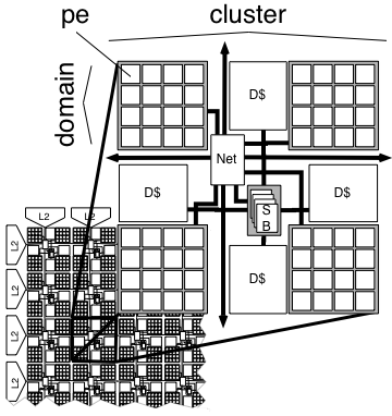
In this section, we outline the design of a small WaveCache that could be built within the next 5-10 years to execute WaveScalar binaries. The WaveCache is a grid of approximately 2K processing elements (PEs) arranged into clusters of 16. Each PE contains logic to control instruction placement and execution, input and output queues for instruction operands, communication logic, and a functional unit.
Each PE contains buffering and storage for 8 different instructions, bringing the total WaveCache capacity to 16 thousand instructions -- equivalent to a 64KB instruction cache in a modern RISC machine. The input queues for each input require only one write and one read port and as few as 2 entries per instruction, or 16 entries total. The input queues are indexed relative to the current wave and a small, multi-ported RAM holds full-empty bits for each entry in the input queues. Matching logic accesses and updates the bits as new inputs arrive, obviating the need for content addressable memories.
In addition to the instruction operand queues, the WaveCache contains a store buffer and a traditional L1 data cache for each 4 clusters of PEs. The caches access DRAM through a conventional, unified, non-intelligent L2 cache. Total storage in the WaveCache is close to 4MB when input and output queues and the L1 data caches are accounted for.
Within a cluster, the processing elements communicate via a set of shared buses. Tiles within the same cluster receive results at the end of the clock cycle during which they were computed. Cluster size is one of the key architectural parameters of the WaveCache. Larger clusters require more wires and more area for intra-cluster communication, while smaller clusters increase inter-cluster communication costs.
For inter-cluster communication, the WaveCache uses a dynamically routed on-chip network. Each ``hop'' in the network crosses one cluster and takes a single cycle.
During execution, each instruction is bound to a processing element, where it remains for possibly millions of executions. Good instruction placement is paramount for optimal performance, because communication latency depends on instruction placement.
Our initial design uses a distributed store buffer. Each set of 4 processing element clusters contains a store buffer shared among 64 functional units. Each dynamic wave is bound to one of these, and all the memory requests for the wave go to that store buffer. As a store buffer completes, it signals the store buffer for the next wave to proceed. This scheme allows the store buffer to be logically centralized but to migrate around the WaveCache as needed.
The remaining difficulty is how to assign store buffers to waves. We propose two different solutions. The first is to add an instruction, \memcoordinate, that acquires a store buffer on behalf of its wave and passes the name of the store buffer to the memory instructions in the wave. This forces a dependency between the \memcoordinate\ and all memory operations, slightly reducing parallelism.
The second solution uses a hash table kept in main memory that maps wave numbers to store buffers. Memory instructions then send their requests to the nearest store buffer. The store buffer accesses the map to determine where the message should go. If the current wave does not yet have a store buffer, the store buffer uses the cache coherence system to get exclusive access to the wave's entry in the hash, fills it with its own location, and processes the request. If the map already has an entry for the current wave, it forwards the message to the appropriate store buffer. While this scheme does not reduce parallelism in the dataflow graph, it places additional pressure on the memory system and adds complexity to the store buffer.